線上影音
Home > ANSYS Designer 教學> 眼圖分析與IBIS-AMI -- Transient Analysis, QuickEye, VerifEye and IBIS-AMI Analysis
本文始於2011,分別於2014、2016、2022更新,以Designer circuit示範不同的眼圖分析方法,除了附上2022R2範例,還總結各種模擬方法的適用情境。另外含等化器FFE(Feed-Forward Equalization)設定,討論IBIS超頻(over clocking)對模擬結果的影響...等延伸議題。
-
Transient Analysis
-
Quick Eye Analysis
4.3 Run analysis, plot eye and contour
4.5 Run analysis, plot eye and contour (no FFE vs. 3-tap FFE)
-
Verify Eye Analysis
5.1 選擇與設置元件
5.3 Run analysis, report bathtub
5.4 Set FFE properties
5.5 Run analysis, report bathtub (no FFE vs. 3-taps FFE for 400mm length)
-
Combine All Eye Analysis
-
IBIS-AMI Analysis
7.3 Add Solution Options
7.4 Run analysis, then report Initial
-
問題與討論 (Q&A)
9.4 如何判別IBIS是否支持"Power-Aware"?
9.5 如何判定一個IBIS模型是不是open-drain?
9.7 "EYEPROBE" and "EYESCOPE"的差異是什麼?
9.8 IBIS-AMI是什麼? 其與IBIS/SPICE模型的差異是?
9.9 為何4.3.2的transient eye and quick eye明顯不同? (重要)
9.10 Designer circuit支持AMI repeater(redriver/retimer)嗎?
9.11 IBIS模型的超頻(over clocking issue) 問題是什麼意思? (重要)
9.12 Transient Analysis與Quick Eye Analysis的差異是什麼?
9.13 如何產生IBIS/IBIS-AMI模型? 從SPICE模型轉出來的嗎?
9.14 為何一些IBIS-AMI模型可能在不同家工具呈現不同結果?
9.15 IBIS模型內的參數 "Automatic delay removal" 是什麼作用? (重要)
9.16 對於IBIS-AMI,wave after source/channel/probe分別位置是?
9.17 Quick Eye在使用時存在許多限制,它有沒有什麼獨特的優點? (重要)
9.18 什麼原因導致Nexxim與HSPICE模擬同一IBIS時,可能結果不同?
9.19 為何移除通道與封裝後wave after source and after channel仍然不同?
9.20 AMI結果以[Eye Diagram Report]或[Statistical Eye Report]畫,有什差異嗎?
![]()
- Transient Analysis
Work with IBIS Model (behavior level):模擬速度快,準度隨著IBIS版本演進(4.x/5.x/6.x/7.1...)越來越好
Work with SPICE Model (transistor level):模擬速度較慢,準度極佳
 Designer circuit自R17.1 (2016.1)起,支持IBIS內的RLC package models (.pkg)。
 - Quick Eye Analysis
Quick Eye使用step response (low-high and high-low)與piece-wise linear pattern做convolution,也就是存在LTI假設。模擬速度快,可以模擬IBIS,但不宜模擬IBIS-AMI model。(但用IBIS跑Quick Eye其實也違反了Quick Eye的LTI假設)
HELP內是這麼說的:Quick Eye analysis employs pattern-dependent convolution. QuickEye uses a brief transient simulation to calculate the channel's step responses to a single rising edge and a single falling edge. QuickEye combines the step responses with the data stream to approximate the output of the channel. The eye diagram is formed by overlaying UIs in the usual manner. With QuickEye, the effect of inter-symbol interference (ISI) on the bit error rate is easy to calculate.
- Verify Eye Analysis
使用統計(statistical)的方法分析BER (Bit Error Rate)、浴缸圖(bathtub),模擬速度快,可以模擬IBIS或IBIS-AMI model。
HELP內是這麼說的:VerifEye analysis is a statistical eye-analysis algorithm. VerifEye also calculates the rising and falling edge responses. VerifEye calculates the probability density function (PDF) for the receiver voltage, taking into account the conditional probabilities for the various kinds of transitions. The BER at a given sample time is the proportion of the voltage PDF that results in an incorrect bit being read. A plot of the BERs over all sample times generates the familiar bathtub curve.VerifEye simulates transmit jitter by adding the jitter distribution to the PDFs for the edge responses.
- IBIS-AMI Analysis
IBIS-AMI Analysis使用Impulse response與piece-wise linear pattern做convolution,可以模擬IBIS-AMI,但不能模擬SPICE model。
HELP內是這麼說的:Reports include plots of step responses from VerifEye, eye diagrams like those available for QuickEye, and bit-error-rate (BER) contours.
 一組完整的IBIS-AMI model其實包含了兩部份:一是傳統的IBIS (.ibs),二是AMI (.ami and .dll)。
前者描述IO基本的驅動特性,如I/V table, V(t) curve,後者用以描述IC內EQ行為。Transient analysis使用傳統IBIS即可運行,而AMI analysis / Verify Eye會用到AMI .dll.
一組完整的IBIS-AMI model其實包含了兩部份:一是傳統的IBIS (.ibs),二是AMI (.ami and .dll)。
前者描述IO基本的驅動特性,如I/V table, V(t) curve,後者用以描述IC內EQ行為。Transient analysis使用傳統IBIS即可運行,而AMI analysis / Verify Eye會用到AMI .dll.可以透過文字編輯器檢視IBIS model,看看其中是否含有[Algorithmic Model] key word,以辨別您的model是否是IBIS-AMI。
 如果你拿到的IBIS model有[Algorithmic Model]語法,但你卻沒有拿到.ami與.dll檔案,那你還是可以跑Transient analysis,但不能跑AMI analysis,也無法使用/模擬該IBIS-AMI model可能有的IC端EQ效應,因為這些描述/定義是被包含在.dll內。
 -
從[Project] \ [Insert Circuit Design]

或如下新建一個circuit design


- Transient Analysis
3.1 選擇與設置元件

Open Micron DDR3 IBIS Model v89c.ibs, and import DQS differential pair


 從 [Pin Import]匯入才有含(考慮)IBIS內per pin RLC(上圖左)或[Package Model](上圖右)所定義的封裝寄生效應,然而從 [Buffer Import]就沒有。如果想比對Designer circuit與其他電路模擬軟體(ADS或HSPICE)對同一個IBIS的模擬結果,這匯入步驟的差異要特別留意。
匯入兩個DQS pair buffer,左邊稍後設為Tx,右邊如下翻面稍後設為Rx

[Components] tab \ [Nexxim Circuit Elements] \ [Distributed] \ [Stripline] \ [Coupled lines] \ [SL_MCPL_DIFF] or [SL_MCPL02_Ref]

以滑鼠左鍵點擊上圖電路符號的接點(小方塊),就可以輕易做電路連接。
雙擊左邊的IBIS模型符號設定:電源為IBIS內部定義的理想電源(此例1.5V),且兩個DQS都選1600MHz速度的模型

 There are different methods to implement ODT effect in IBIS, for example, Micron uses [add submodel] grammar.
左邊buffer如下設[Output Buffer]作為Tx,右邊buffer設[Input Buffer]作為Rx

 請注意,上圖的pkg_selector內的[Package][Pin]選項,分別是如下在.ibs內定義的封裝寄生參數 (非較完整的Package Model)
在Tx端設定要激發的訊號型態(Random bit/PRBS pattern),訊號寬度與上升下降時間

上圖的上升/下降時間(trise/tfall),並非指IBIS"真實輸出"訊號的上升/下降時間(50~100ps),而是指激發IBIS模型的"理想輸入"驅動訊號的上升/下降時間(1~10ps)。輸出訊號真正的上升/下降時間應該是由IBIS模型內所定義的Rising Waveform/Falling Waveform特性所決定,而不是由使用者輸入來決定。所以上圖輸入的Tr/Tf要遠小於真正輸出訊號的Tr/Tf,才不會影響模擬結果,這是初學者很容意誤解的地方,請注意。
 從2023R2起,Designer circuit設定IBIS的[Bit]標籤下,移除了上升/下降時間設定項。此時IBIS輸出訊號的上升/下降時間除了由模型特性所決定,還與AMI Analysis setup內的UI/(samples per bit)有關。(Transient,QEye Analysis則是默認用UI/64)
"Random bit"是可以指定seed的隨機樣式。而PRBS除了可以指定seed,還是一個在指定長度內循環的隨機樣式。PRBS-N表示2N-1長度的pseudo random bit patterns。
3.2 設置Transient Analysis

[Circuit] \ [Add Nexxim Solution Setup] \ [Transient Analysis]


3.3 Run analysis, then report

- Verify Eye Analysis
5.1 選擇與設置元件,同step 4.1
5.2 設置Verify Eye analysis


5.3 Run analysis, report bathtub

-
Combine All Eye Analysis
-
IBIS-AMI Analysis
- 總結

- 問題與討論
-
Two inconsistent waveform table definitions for [Raising Waveform] and [Falling Waveform].
兩個彼此有衝突的waveform定義。這類型的錯誤,一般的Virtual IBIS Editor也無法顯示waveform,可以人工肉眼搜尋檢查keyword [Raising Waveform]與[Falling Waveform]的內容是否存在不合理之處。
一個正確的IBIS內會包含兩組Rising waveform與兩組Falling waveform定義(共四組波形),其分別是以50 ohm上拉與下拉電阻的測試條件,描述I/O的上升與下降波形。
-
steady state endpoint of [Raising Waveform] is inconsistent with pullup I/V table
-
An expected condition should be:C_comp = C_comp_pullup + C_comp_pulldown
-
[pkg_selector]參數用以選擇每支pin腳的RLC定義,但並不是[Package Model]內的定義。[pkg_selector1] and [pkg_selector2]分別對應 differential pair的兩根pin。
-
只有使用 [Package Model] (refer to 3.1),Nexxim才有考慮每根腳間的coupled RLC寄生效應(互容互感)。 當 [Package Model]被使用時, [pkg_selector] 的設定就會忽略。
- Quick Eye is based on LTI (linear time invariant) assumption, but IBIS is non-linear model. So, for the case with IBIS model, transient eye is more accurate than quick eye.
- Make sure [step_resp_num_ui] is large enough for step\impulse response to settle.
- 跑的是IBIS model "slow" corner,而非一般的 "typ" corner
- Over clocking (超頻) IBIS model. 比方說,以3.3GHz的輸入訊號驅動DDRIII-2133 IBIS model,即超頻使用IBIS model
-
一些較新的指令,像[Back-Channel],Designer還未支持。另外Agilent、SiSoft常先做自己支持的AMI model。[5]
- AMI Analysis Setup內的Time Step值沒設好會有影響,值設小一點,會有幫助. Both of the setting as below will be fine
- 須確保Impulse response是settle的
- Designer/Nexxim simulate with package RLC by default, but HSPICE not.
- HSPICE deals with "over clocking" issue automatically, but Designer/Nexxim not yet. Users have to set rm_dly_xxx=-1 manually, to remove "flat" delay time. Refer to 9.11 or another article
- The Logic_in (bit pattern) for an IBIS buffer should have a range of 0V to 1V. IBIS buffers have fixed logic thresholds of .2V and .8V. Use of an Input signal other than 0V to 1V can cause duty cycle distortion (DCD).
-
既然IBIS-AMI不能模擬SSN,也沒有對不同EQ時的電流定義,那IBIS-AMI的I/O如何做SI+PI的co-simulation?
這題是有鑑別度的,... 但答案其實很簡單(提示:回答只需六個字母)。
簡答:CPM+AMI (請將此行反白就可以看到簡答)
詳答:(請將下段落反白就可以看到詳答)
- 參考

Analyze icon
or [F10]
[Circuit] \ [Results] \ [Create Eye Diagram Report] \ [Rectangular Plot]

除了以訊號相減來得到差分訊號眼圖,也可以使用內建的differential voltage probe : [Components] tab \ [Nexxim Circuit Elements] \ [Probes] \ [VPROBE_DIFF]來直接量得眼圖訊號

[Windowing]與[Thinning]這兩個選項,前者以模擬的起始與終止時間當作plot range,是默認選項也最直覺,但其有最多1e+8個取樣點的限制。打個比方說 :若設start time 0, stop time 10ms, 則time step不能小於10ps,如果time step設1ps,那當你plot 0~10ms的時域波形,軟體會只印出9~10ms,除非你改選[Thinning]這選項。
4.1 選擇與設置元件 ![]()
同第步驟三的設定,但增加了EYESOURCE與EYESOURCE_DIFF
[Components] tab \ [Nexxim Circuit Elements] \ [Independent Sources] \ [EYESOURCE]
[Components] tab \ [Nexxim Circuit Elements] \ [Probes] \ [EYEPROBE_DIFF]

IBIS QuickEye/VerifyEye需要有EYESOURCE與EYEPROBE才能運作,但IBIS-AMI QuickEye/VerifyEye不需要EYESOURCE與EYEPROBE直接就能跑。
Quick Eye Analysis不宜跑IBIS-AMI分析,2022R2會有如下警告訊息

重新設置IBIS內的訊號來源,改成從外部的 EYESOURCE饋入,這樣接收端就可以放EYEPROBE,讓QuickEye分析可以抓到結果

4.2 設置Quick Eye analysis ![]()
4.3 Run analysis, plot eye and contour ![]()
4.3.1 Analyze icon
or [F10]
後處理折疊得到眼圖:[Circuit] \ [Results] \ [Create Eye Diagram Report] \ [Rectangular Plot]


統計概念處理的眼圖:[Circuit] \ [Results] \ [Create Statistical Eye Report] \ [Statistical Eye Plot]

4.3.2 此例雖然線長20mm時,3.3 Transient Eye與4.3 Quick Eye做的眼圖看起來很像,但此例隨著線長增加到50~100mm,兩種模擬方法差異就會越來越明顯。這背後反應的是以Quick Eye模擬IBIS其實違反了LTI假設。


[Circuit] \ [Results] \ [Create Standard Report] \ [Rectangular Contour Plot]


4.4 Set FFE properties ![]()
在開始測試FFE前,先把通道線長從20mm加長400mm,UI從625mm改小成468ps (DDR3-2133),先跑一次沒有FFE的Quick Eye。
再雙擊 [EYESOURCE_DIFF] 設定 [FFE_data] with the [Number of Taps]如下,跑一次有FFE的Quick Eye

[Number of Taps]可以指定0~N的任意整數,當指定0時表示沒有FFE (Feed-Forward Equalization)效果,指定3則表示three-taps FFE。
Designer(Nexxim)計算FFE時,默認會幫你自動調配各tap的weight,而location 0那一個tap的權重always會是最高的,因為它代表時間軸上當下時間(bit time)位置的訊號大小權重。
並且當QuickEye分析結束時,Designer會將calculate的各tap weight結果顯示在message window(R17.2)或log file(R18.2~),如下圖所示(location, weight)

4.5 Run analysis , plot eye and contour (no FFE vs 3-taps FFE) ![]()
確實可以看出有3-tap FFE的眼圖張開略好


2022R2的Contour不能透過Eye Measurements顯示MinEyeWidth/MinEyeHeight?
此問題在2021R2不存在,且於2023R1修正。
Analyze icon
or [F10]
[Circuit] \ [Results] \ [Create Standard Report] \ [Rectangular Contour Plot]


如果你以2022R2, 2023R1畫的Bathtub縱軸座標顯示數值有問題(2021R2, 2023R2則是正常),請把Y軸顯示屬性內的[Number Formate]從[Auto]改[Scientific]即可。
5.4 Set FFE properties as the same as step 4.4
5.5 Run analysis, then report bathtub (no FFE vs 3-taps FFE for 800mm length) ![]()


![]() 為避免使用者混淆,誤以為VerifyEyeAnalysis畫的眼圖(Statistical Eye)其Inner eye contours指的就是EBR contours,自2022R2起VerifyEyeAnalysis僅提供BER(Bath Tub)與Contours的顯示方式,移除了畫眼圖的功能。VerifyEyeAnalysis畫的眼圖是bit-by-bit pattern得到的Probability Mass Function (PMF) data,其Inner eye (contours)是依測試pattern所得的worst-case waveform與BER data基於機率分佈的統計結果得到的contours不同。
為避免使用者混淆,誤以為VerifyEyeAnalysis畫的眼圖(Statistical Eye)其Inner eye contours指的就是EBR contours,自2022R2起VerifyEyeAnalysis僅提供BER(Bath Tub)與Contours的顯示方式,移除了畫眼圖的功能。VerifyEyeAnalysis畫的眼圖是bit-by-bit pattern得到的Probability Mass Function (PMF) data,其Inner eye (contours)是依測試pattern所得的worst-case waveform與BER data基於機率分佈的統計結果得到的contours不同。
6.1 選擇與設置元件 ![]()
[Components] tab \ [Nexxim Circuit Elements] \ [Independent Source] \ [MultiCompContainer_1pin]

如果上圖步驟五內沒有可選擇的分析選項,請先[Add Analysis Setting]


6.2 Setup and run all of the analysis ![]()

可透過雙擊或[File] \ [Restore Archive]打開下載附件"L01_EYE_Example_Release_22R2.aedtz".
裡面含一個IBIS-AMI_Models資料夾,內有IBIS-AMI模型可供練習。
7.1 新建一個circuit design,並以3.1所示的步驟匯入IBIS-AMI的Tx與Rx ![]()


一組完整的IBIS-AMI模型須包含.ibs、.ami與.dll。這三個檔案須放在同一個目錄下,這樣軟體在匯入.ibs時就會自動帶入.ami與.dll。
萬一你拿到的整包IBIS-AMI只有xxx_w32.dll沒有xxx_w64.dll,不用擔心64bit OS也能運作,但要確定xxx.ibs內定義的所有檔案都有。
檢視IBIS-AMI模型內的FFE/DFE等化器(Equalization/Pre-emphasis)參數,這些參數是由模型供應商決定,對應正確的.ami, .dll才能運作。
以上你在Designer circuit的UI內看到的AMI參數默認值,定義在xxx.ami內
7.2 設置AMI Analysis ![]()
[Circuit] \ [Add Nexxim Solution Setup] \ [AMI Analysis]
7.3 Add Solution Options
[Circuit] \ [Add Nexxim Solution Options] ... 默認可不加(非必要)
7.4 Run analysis , then report Initial Response (Impulse Response) ![]()
[Create Stand Report] \ [Rectangular Plot]


If you want to extend the simulation time period for the impulse response, increase the [step_resp_num_ui] parameter in Tx model.
[step_resp_num_ui] 必須夠大以確保 impulse response到達穩定,這對AMI準度很重要。默認 [step_resp_num_ui]=100*UI
輸入Jitter效應時,要注意其默認單位不同 : dcd=0.1 (means 0.1*UI), but txrj=1e-11 (means 10ps)
7.5 Report waveform after receiver ![]()
7.5.1 [Create Statistical Eye Report] \ [Statistical Eye Plot] (InitialEye)

[Create Statistical Eye Report] \ [Statistical Eye Plot] (EyeAfterProbe)

7.5.2 調整FFE等化器參數如下

對於AMI分析,使用statistical eye plot會比regular eye (eye diagram report)好。 Refer to 9.20
此例以2022R2的AMI analysis與Verify Eye analysis畫的BER contour不同,這問題會在2023R1修正。
7.6 Cross-talk using IBIS-AMI ![]()
AMI analysis可以考慮crosstalk嗎?
答案是可以的,以下簡單測試證明。


| 分析引擎 | 適用情境 |
| Verify Eye Analysis | BER Contours, Bathtub |
| AMI Analysis | IBIS-AMI Eye (should use statistical eye plot because it includes the effects of recovered clock jitter returned by the Rx model, and it automatically ignores the "Ignore_bits" bits), BER Contours, Bathtub |
| Transient / Quick Eye Analysis | Plain IBIS devices Eye (can use regular eye (post-processed by UI) or statistical eye). BER Contours, Bathtub work with Quick Eye. |
9.1 如何對IBIS模擬波形除錯? ![]()
Ans:這幾年用IBIS做模擬很"流行",IBIS建模軟體也有好幾家,但不知道是軟體的問題還是使用者操作不當(我相信是後者),SI engineer很有機會拿到一個未經充分驗證(含語法/定義衝突)的IBIS模型。這年頭你拿到的IBIS model,如果沒有完善的使用說明與驗證報告(如美光的完整模型包),不一定是可信賴的。最保險的方法,可以上IBIS協會官網,下載official IBIS6 parse checker或使用SPISim做IBIS/IBIS-AMI語法檢查。
幾個常見的基本錯誤排行榜

如果IBIS maker搞烏龍,在產生這四組波形時出錯(比方,兩組Rising waveform長的一樣,即不管是外掛上拉或下拉50 ohm,波形最高電壓居然相同?),會造成Designer circuit無法正確模擬。此時, 就需要將Ramp_fwf, Ramp_rwf改成0或1才可以運行。
ramp_rwf and ramp_fwf parameter =1 表示只使用第一組waveform (無視第二組waveform定義)
ramp_rwf and ramp_fwf parameter =0 表示產生I/O output waveform的過程, 不透過IBIS內的waveform定義生成, 只透過最簡略的[Ramp]斜率定義
9.2 HPC可以加速眼圖模擬嗎? ![]()
Ans:可以,但只對Transient Analysis作用,稱為TPBS (Transient Parallel Bus Speedup)。
啟動方式
有作用時會在模擬過程看到以下訊息
9.3 FFE是什麼? 該如何設定較好? ![]()
Ans:HELP內有很好FFE的"原理"與使用說明,節錄部份內容如下:
The cursor locations are sample points in the step response over the number of unit intervals (UI) equal to the number of taps. Cursor 0 is the main cursor, whose weight affects the value of the current bit. By default, Tap 1 is at cursor location 0, the main cursor.
By default, Nexxim calculates the tap weights from the (unequalized) step response. The algorithm always places the largest tap weight at location 0. For weights calculated by Nexxim, normalization is always performed such that the sum of the absolute values of all the weights is equal to one.
有興趣的讀者也可以參考台大吳瑞北教授的講義[8]
一般two-tap FFE即可得到明顯的SI改善效果,但three-tap FFE會更好,原因是three-tap的EQ調整可以涵蓋前一個與下一個時間的響應。我們以步驟4.4的範例示範


取FFE的taps數為奇數,且位置從location 0時間點前後對稱延伸,如下所示設定有時會較好。(雖然此例沒有較好)

大部分的情況讓軟體自動計算權重的效果就很好了,自行指定權重的效果不一定較好。(雖然有時會較好)
9.4 如何判別IBIS是否支持"Power-Aware"? ![]()
Ans:"Power Aware"是IBIS v5.0起支持的語法,可搜尋.ibs內是否含關鍵字[Composite Current]
9.5 如何判定一個IBIS模型是不是open-drain? ![]()
Ans:有時候我們會遇到IBIS無法把輸出拉到正確電壓位準的情況,而這是由於它是 "open-drain"模型所致。
有一個簡單的方法可以知道一個IBIS模型是不是open-drain:如果IBIS內不含 [Pullup] 與 [Power Clamp]定義,Model_type定義為[open_drain]或[open_sink], 它就是open-drain,使用者必須自行外加上拉電阻。
可以去美光官網下載DDR4 IBIS model,這是個很好的IBIS模型,包含一般IOs (as DQL,DQH,DQSL,DQSH)與 open-drain (as ALERT)
以本例而言,Designer匯入此Micron DDR4 IBIS model,選擇ALERT buffer後,顯示該buffer是open_sink而不是寫open_drain,這主要是因為在[Model]這語法關鍵字下定義的Model_type你怎麼寫
9.6 如何移除IBIS模型裡所定義的封裝RLC效應? ![]()
Ans:

Designer circuit從R16起支持die-side node與board-side node,且自R17.1起支持 [Package Model] from R17.1。而die-side probe只支持於Transient Analysis,如下所示:

In case you can't find [pkg_selector] term in the IBIS properties, please make sure to import IBIS model from [Pin Import] tab, not [Buffer Import] tab in step 3.1.1.
請注意:die-side probe與不考慮package RLC寄生效應是兩件事。
9.7 "EYEPROBE" and "EYESCOPE"的差異是什麼? ![]()
Ans:
Eye probe搭配對應的Eye source一起運作,以得到VerifEye, QuickEye, or Transient analysis。
Eye scope可以量transient analysis不同位置的眼圖。
If a user would like to do transient analysis and plot "statistical eye" with "delay to start of recording" (as the "offset" parameter in regular eye plot), just [EYESCOPE] can perform that.
9.8 IBIS-AMI是什麼? 其與IBIS/SPICE模型的差異是? ![]()
Ans:IBIS-AMI比起IBIS多了EQ與跨平台加密能力,更適合高速SerDes模擬,且模擬速度比起SPICE快許多,可說是兼具IBIS與SPICE兩者的優點。
但必須注意:IBIS-AMI (AMI analysis)不適合做SSN/SSO模擬,即使Power-aware IBIS (Transient analysis)可以。原因是
-- AMI analysis/QuickEYE/VerifyEYE(Statistic analysis)是基於LTI(Linear Time Inverient)線性非時變的假設,而IBIS是non-linear模型。
-- 目前IBIS-AMI還沒有定義非理想的PDN對EQ的影響該如何處理
Refer to [4] What is IBIS-AMI by SPISIM
9.9 為何4.3.2的transient eye and quick eye明顯不同? ![]()
Ans:Two points should be noted
9.10 Designer circuit支持AMI repeater(redriver/retimer)嗎? ![]()
Ans:Yes, it supports repeater from 2015.

Redriver與Retimer效果差不多,要驗證Repeater模擬結果對不對的簡單方法:把一段線接成兩段線,看看結果是否跟一段線長度的結果一樣,如下圖所示:中間穿插repeater (redriver/retimer),可看到傳輸線長度加倍,但眼圖張開的程度幾乎不受影響。

For re-driver, "eye after probe" of Rx1 should be the same as the "initial eye" of Tx2
Redriver Tx is continuously driven by redriver Rx's analog output signal, it is inefficient to model recovered clocks and digital signal in retimer. [1], p.5
Retimer Rx model must implement AMI_GetWave function, and the function must return clock times. Simulator samples retimer Rx Getwave's output signal at 0.5UI after each clock time returned by Rx, generates the digital stimulus that drives retimer Tx. [1], p.7
9.11 IBIS模型的超頻(over clocking issue) 問題是什麼意思? ![]()
Ans:
如果使用者超頻使用IBIS模型(即輸入訊號速度高於模型輸出可以反應的速度),那(相對於SPICE模型)不預期的不連續輸出訊號就會發生,又各家軟體對超頻發生時的模擬結果可能不同。這是因為IBIS模型不像SPICE (transistor-level)可以正確處理超頻(IBIS並未定義超頻使用下的處理方式)。
詳情可查詢Designer circuit HELP關鍵字"Transition Settling Times"或"Avoid Overclocking Drivers":這主要跟IBIS model內定義的V-T table還有initial delay有關。使用者必須確保模擬的UI (Unit Interval) ³ V-T duration (window),或是說:確保下一個bit轉態時間發生在V-T尾端穩態的區域內。
以Micron IBIS模型為例說明,下圖2133MHz的模型所定義的V-T duration是469ps,所以模擬的速度不應超過1/469ps@2133MHz
有兩種使用情況較易遇到over clocking:
下圖是Micron DDRIII-2133 IBIS model,但卻以UI=300ps的時序激發模擬(UI<V-T duration),這樣的模擬結果到底對不對?

以此例來說, 這模擬結果"堪用"。
從V-T table來看:for typical corner, waveform is not settled until 380ps (but, not for slow corner, it is not settled until 450ps),所以若在300ps發生下一個bit的轉態,並不會造成輸出波形"明顯的"不連續

Setting rm_dly_rwf=rm_dly_fwf=20ps or set rm_dly_rwf=rm_dly_fwf=-1ps, you will get almost the same waveform as above result.

此例的IBIS model有個特點,其initial delay特別短(10~20ps),所以如果採用一般以縮短initial delay來達到model加速的效果反而會要小心,不然會出事:此例rm_dly_不能設超過20p. To avoid the "overclocking" issue, manually set the RM_DLY_RWF or RM_DLY_FWF to positive values that represent the amount of time to trim from the front of the transition waveform. Doing this, however, will affect the overall timing of the output waveform (time shift).
The result below is with RM_DLY_RWF=RM_DLY_FWF=169p (wrong)
如果硬是砍掉initial delay 169ps以滿足UI>V-T duration,雖然眼圖開的很漂亮,但這已經忽略掉非穩態的部分,所得到的結果是錯的. refer to AN007

IBIS VT Waveform and Over Clocking
Initial Time Delay Issue in IBIS VT Curves
Over-Clocking model validation
IBIS BIRD 168.1 [Initial_Delay] -- Handling of Overclocking Caused by Delay in Waveform Data
http://www.ele.uri.edu/
courses/ele448/HspiceRef/ hspice_si.pdf , p.237 , rm_dly_rwf | rm_dly_fwf
9.12 Transient Analysis與Quick Eye Analysis的差異是什麼? ![]()
Ans:Quick Eye可以直接用IBIS,但無法直接用SPICE model
Quick Eye模擬速度快許多,特別適用於simulate very large bit count to plot eye diagram,且Quick Eye source內可直接參數化加入jitter與equalization的效果
在Nexxim Solution Option中,[Eye Options]是關於Quick Eye與VerifEye Analysis的設定控制,不影響Transient Analysis
9.13 如何產生IBIS/IBIS-AMI模型? 從SPICE模型轉出來的嗎? ![]()
Ans:
ANSYS generates IBIS-AMI by [SPISim], which is able to create IBIS-AMI from system level description or SPICE model. refer to here
Agilent generates IBIS-AMI by [SystemVue], not ADS directly. It generates IBIS-AMI model based on system level description with parameters that user define, not SPICE file. Refer to here
9.14為何一些IBIS-AMI模型可能在不同家工具呈現不同結果? [10] ![]()
Ans:常見有幾個原因


9.15 IBIS模型內的參數 "Automatic delay removal" 是什麼作用? ![]()
Ans:For initial delay, IBIS model provides four parameters to compensate, they are rm_dly_rwf, rm_dly_fwf, rm_tail_rwf, rm_tail_fwf and they are zero by default. 記得前兩個值如果要設,設負值才會"自動"調整
Automatic delay removal. Some IBIS models represent the throughput delay of the device by providing model waveforms with long initial plateaus, after which the device is switched at a much shorter period corresponding to the actual slew rate. ... Using RM_DLY_RWF and RM_DLY_FWF to manually trim the initial delay ... . In addition, the overall timing of the simulation is shifted by simply trimming the waveforms.
Setting either RM_DLY_RWF or RM_DLY_FWF to a negative value (<0) invokes automatic delay removal for both rising and falling waveforms. The initial delay plateau is computed for each waveform in a given device's IBIS model. The common delay is the minimum of the values computed for all waveforms for the selected corner case (typ, min, max, fast, slow). The common delay time is removed from the beginning of each waveform. ...總結來說:IBIS model如果要超頻使用,或是因為使用slow corner得到與SPICE不同的結果(表示model maker沒把關好),盡量透過rm_dly_rwf, rm_dly_fwf設負值讓軟體自動幫你補償優化(remove initial delay),如果要自己手動調整rm_dly_rwf, rm_dly_fwf設正值,則必須確保所移除的data是在穩態範圍內(即initial delay要夠長,移除的部分不能影響到暫態),最後再以SPICE做correlation。非必要不要隨便做V-T removal。
9.16 對於IBIS-AMI,wave after source/channel/probe分別位置是? ![]()
Ans:
沒遇過IBIS-AMI模型中在IBIS尾端附[Package Model]來表示封裝寄生效應的,大部份是以在.ami中連結外部S參數的方式來表現on-die寄生效應,或直接附上.snp讓使用者於電路模擬時自行連結。此外,多次發現IBIS-AMI內夾帶的S參數本身存在無緣性與因果性違規,很容導致模擬波形失準或不收斂,當中不乏大廠提供的模型。
上圖中即使不考慮封裝與Interconnect(channel)的部分,把IBIS-AMI的Tx與Rx端直接對接(pass-through connecting),通常會看到[Wave after Source]與[Wave after Channel]波形仍然不同。這是因為[Wave after Source]是由IBIS Tx的Impulse response得到,[Wave after Channel]是由IBIS Rx的Impulse response得到,除非你拿到Tx/Rx特性正好可以得到完全相同的Impulse response,否則無法期待直接把Tx buffer與Rx buffer對接可以得到相同的波形。簡言之,雖然看上圖把IBIS Tx, Rx buffer對接是把[Wave after Source]與[Wave after Channel]短路,但其實它不是理想的短路概念,而是分別來自Tx與Rx buffer定義的特性。
不論是wave after source/channel/probe的哪一種,都不是波形量測探針可以接觸的(IC外部pin)節點。
9.17 Quick Eye在使用時存在許多限制,它有沒有什麼獨特的優點? ![]()
Ans:Quick Eye最大的好處是模擬速度快,但使用上存在一些假設(或說是限制limitation)
Quick Eye模擬IBIS時,違反了QE本身的LTI假設,Quick Eye模擬IBIS-AMI時,會忽略其IC端等化器演算法,這也不行那也不行,它有甚麼獨特的好處?
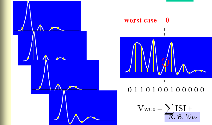
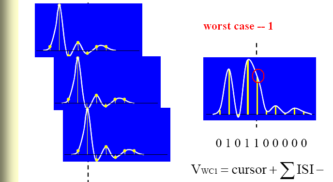
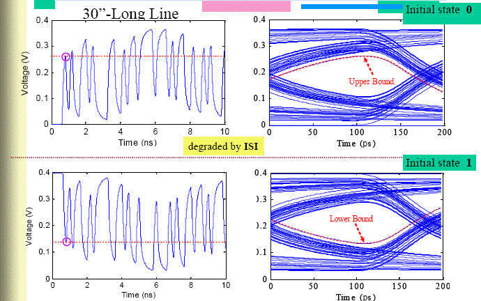
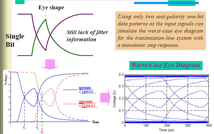
Quick Eye可以模擬最糟情況 (Peak distortion analysis, PDA):PDA calculates the worst case bit pattern [9] from the step responses of the channel. Peak distortion analysis is calculated for each combination of Eye Source and Eye Probe.


9.18 什麼原因導致Nexxim與HSPICE模擬同一IBIS時,可能結果不同? ![]()
Ans:
9.19 為何移除通道與封裝後wave after source and after channel仍然不同? ![]()
Ans:


即使不考慮封裝與Interconnect的部分,把IBIS-AMI的Tx與Rx端直接對接(pass-through connecting),通常會看到[Wave after Source]與[Wave after Channel]波形不同。這是因為[Wave after Source]是由IBIS Tx的Impulse response得到,[Wave after Channel]是由IBIS Rx的Impulse response得到,除非你拿到Tx/Rx特性正好可以得到完全相同的Impulse response,否則無法期待直接把Tx buffer與Rx buffer對接可以得到相同的波形。簡言之,雖然看上圖把IBIS Tx, Rx buffer對接是把[Wave after Source]與[Wave after Channel]短路,但其實它不是理想的短路概念,而是分別還含有Tx與Rx buffer的影響。
9.20 AMI結果以[Eye Diagram Report]或[Statistical Eye Report]畫,有什差異嗎? ![]()
Ans:左邊[Eye Diagram Report] MinEyeWidth=118ps,右邊[Statistical Eye Report] MinEyeWidth=160*0.7365=117.8ps

Only [Eye Diagram Report] can plot "Rectangular Plot"

[Eye Diagram Report] can plot eye diagram with offset, but [Statistical Eye Report] plot eye considering [ignore_bit] automatically, instead of the [offset] parameter.


[Statistical Eye Report] can plot eye diagram with honoring [Ignore_Bit] of AMI Rx model, instead of setting offset in [Eye Diagram Report].
[Ignore_Bits]是Rx端的參數(Tx沒有),其默認值由模型建立者定義在Rx.ami內,表示AMI內部需要多少時間讓訊號反應穩定(e.g. how long the CDR model takes to lock)。這參數很少需要使用者去調整調整,有些模型這值會超大(~50000)。這參數很重要,但只有statistical eye plot會自動考慮這參數。
另外,也只有statistical eye plot才使用從Clock Data Recovery (CDR)得到的returned clock times。
[Init_Returns_Impulse] is used for statistical analysis (impulse response with LTI assumption)
[GetWave_Exists] is used for time-domain bit-by-bit analysis and NLTV (non-linear time variant).
[Max_Init_Aggressors] is a reserved parameter for model writer, not for end user. Don't modify it, too.
Do not enable [Use_Init_Output]. That parameter was deprecated in version 5.1 of the IBIS spec.
一般我們說SI+PI co-simulation包含兩部分:
PI --> SI,就是PI影響SI結果。如IR drop導致眼高變小或是Power/Ground上因(其他)IC動作瞬間電流引起P/G noise導致SI變的較差。
SI --> PI -->SI,就是SI影響PI再回頭影響SI結果。如高速訊號切換的SSN回灌到Power/Ground,而這不乾淨的P/G自然又影響了SI。
所以要回答這問題的前提是,你想要的SI+PI的co-simulation是做到什麼程度?
IBIS-AMI的SI+PI的co-simulation能透過CPM+AMI做到第一項,但第二項目前IBIS-AMI並不支持。
[1] K. H. Chong, V. Avula, F. Rao, "IBIS AMI Modeling of Retimer and Performance Analysis of Retimer based Active Serial Links", DesignCon2014.
[2] M. Bari, F. Rao, "End to end Link Analysis and Optimization with Mid-channel-redriver AMI Models", DesignCon2013.
[3] Designer with Nexxim Statistical Eye Capabilities by Ansoft
[4] What is IBIS-AMI by SiSoft, What is IBIS-AMI by SPISIM
Understanding IBIS-AMI Simulations by SiSoft, DesignCon2015.
Introduction to IBIS-AMI by SiSoft, DesignCon2018.[5] IBIS Spec
IBISCHK6 (Parser語法檢查)
IBIS BIRDs , please note the items that have been accepted
[6] Equalization for High-Speed Serdes, Broadcom Corporation
Equalization for High-Speed Serial Interfaces in Xilinx 7, Xilinx[7] You can find a IBIS-AMI example in ...\AnsysEM15.0\Win64\Examples\Designer\SI_Circuit\AMI_Example.adsn
[8] 台大吳瑞北老師的講義,說明Equalization
Discrete Time Equalizer (digital compensation as Feed-Forward Equalization, FFE), de-emphasis\pre-emphasis
Continuous Time Equalizer (analog compensation as Continuous Time Linear Equalizer, CTLE, a high pass filter), p.11
[9] 台大吳瑞北老師的講義,說明ISI的worst-case bit pattern for fast-eye analysis
[10] IBIS-AMI Model Simulations Over Six EDA Platforms, by XILINX, DesignCon2015.
這篇除了顯示各家IBIS-AMI simulation結果有差外,並沒有結論。筆者推薦的原因是這定性定量分析的邏輯與手法[11] Randy Wolff, "Signal Loop Inductance in [Pin] and [Package Model]", DesignCon IBIS Summit 2010


