線上影音
Home > ANSYS Simplorer教學 > Conducted EMI using Simplorer+Q3D
本文始於2017.08,除了介紹幾篇大廠使用Simplorer+Q3D分析傳導干擾的成功案例外,也示範一個簡單而完整的操作流程,附上檔案供讀者可以學習。The article started in 2017.08. Besides introducing some successful stories of conducted EMI analysis with Simplorer+Q3D, it demonstrates a simple example for user to download and practice.
-- 新增7.3於 2019.12
-
大廠成功案例 Successful Stories
2.1 Rockwell used Simplorer+Q3D for Flyback conductive EMI analysis
2.2 Toshiba used Simplorer+Q3D for DC-AC Inverter conductive EMI analysis
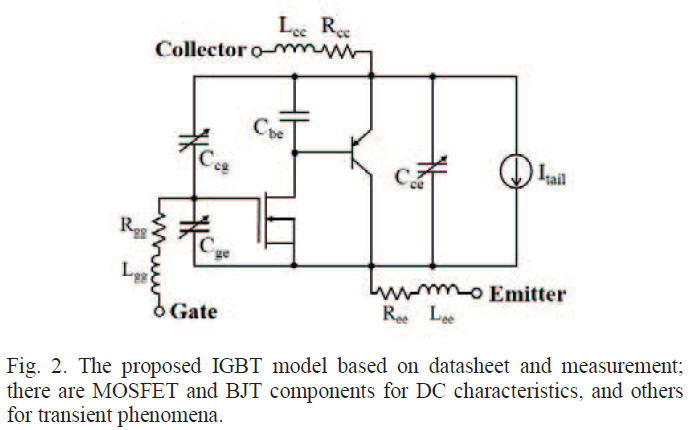
2.3 Power Inverter using accurate IGBT model based on datasheet, Simplorer+Q3D -
含元件動態模型與PCB寄生效應的電路模擬 Circuit Simulation with device dynamic models and PCB parasitic effect
-
含元件動態模型, PCB與封裝寄生效應的電路模擬 Circuit Simulation with device dynamic models, PCB and package parasitic effect
-
問題與討論 Q&A
7.1 模型更準確,在頻域上看到的傳導EMI是變差還是變好呢?
7.2 電源系統中,IC/封裝/PCB/Cable/主動/被動元件的寄生效應,何者影響最大?
7.3 Simplorer連結Q3D模型共有幾種方式?其分別特性與設定注意事項(準度/頻寬)?
7.4 Rectangular Plot時,Domain選[Spectral]為何[Noise Threshold]呈現灰色,無法更改設定60dB成其他?
![]()
-
電力電子模擬 Power Electronics Simulation

一個真實的系統中含有許多大大小小的元件(IC/PCB/Connector/Outer case...),模擬結果要準確除了需考慮每個元件不同層面的影響外(電/熱/應力...),還必須考慮模擬的時間以兼顧工作效率。因為越準確的模型所需的模擬時間越久,所以正確的系統觀點判斷,對於不同的元件採用不同準度/等級的模型來做模擬,才是高明的做法。
也就是說,在開始模擬之前的準備階段,對於所要模擬的題目、想要觀察的問題現象本身的物理特性有基本理解,事先做好評估,採用最理想的模擬手法,這才是做好模擬的關鍵所在。
以電性模擬為例來說,HSPICE model與IBIS model就是兩種不同的IO model,前者是transistor level,比較準但模擬時間較長,後者是behavior model,準度還可以,但模擬速度快很多。另外,RLC model與S-parameter model也是兩種不同的寄生效應模型,前者適用於低頻(conductive EMI)問題分析,後者適用於高頻問題分析(radiative EMI or coupling issue)。
以下是Simplorer支持的各種不同級別的元件模型 :


-
大廠成功案例 Successful Stories
2.1 Rockwell Automation used Simplorer+Q3D for Flyback conductive EMI analysis [1]
模擬準確的關鍵在:系統\電路中所有的主動、被動元件與PCB都要正確的modeling(手法要正確),整個一起模擬得到收斂的結果(選擇對的軟體)。
這篇ppt有很多what if分析,值得研讀,了解人家大廠是怎麼做研究。(不過該內容原本在IEEE EMC Society的連結被移除了)
2.2 Toshiba used Simplorer+Q3D for DC-AC Inverter conductive EMI analysis [2]
除了先前我們提到的主動、被動元件與PCB外,本篇論文還包含cable與功率元件封裝的寄生效應
不管時域或頻域波形,都非常準確
2.3 Power Inverter using accurate IGBT model based on datasheet [3]
利用Q3D萃取PCB model,除了datasheet的資訊,必須再考慮其它RL寄生效應 得到對於暫態響應更精準的model,模擬跟量測會更貼近。


-
基本電路模擬 Basic Circuit Simulation
For the first experience to simulate with Simplorer, let's implement a buck DC-DC converter for example. All of power device models are taken from Simplorer library. If you don't know how to do that, please refer to here.

-
含元件動態模型的電路模擬 Circuit Simulation with device dynamic models
Instead of using system model for power devices, we use dynamic models for the MOS and diode as below.
There are a lot of power device dynamic models ready in Simplorer library.
Comparing the spectrum of Vo using system model and dynamic model.


-
含元件動態模型與PCB寄生效應的電路模擬 Circuit Simulation with device dynamic models and PCB parasitic effect
Use Q3D to extract PCB (5cmx10cm) parasitic RLCG effect
Link Q3D 3D model in Simplorer, from [Simplorer Circuit] \ [Subcircruit] \ [Add Q3D Dynamic component] \ [Add State Space]
Re-arrange the schematic circuit and connect all components correctly.


-
含元件動態模型, PCB與封裝寄生效應的電路模擬 Circuit Simulation with device dynamic models, PCB and package parasitic effect
-
問題與討論 Q&A
7.1 模型更準確,在頻域上看到的傳導EMI是變差還是變好呢?
Ans:2.2與2.3的論文顯示, 使用accuracy power device model,LISN量到的conductive EMI在高頻(1~100MHz)會較低。本文step4,5也有看到同樣的趨勢,使用高準度的dynamic model for power device,高頻(5~27MHz)的conductive EMI是較低的。
7.2 電源系統中,IC/封裝/PCB/Cable/主動/被動元件的寄生效應,何者影響最大?
Ans:從本文的簡單範例,以及論文[2][3]所示,power device使用高準度模型做電力電子模擬,對雜訊結果有關鍵性影響。從[2][4][5]可以看出考慮封裝模型的重要,從[2][6]則可以看到Cable model有很大影響,[7]可以看出PCB的影響,所以都很重要。
7.3 Simplorer連結Q3D模型共有幾種方式?其分別特性與設定注意事項(準度/頻寬)?
Ans:共有五種方式
- 直接透過Simplorer軟體操作畫面連結(Dynamic Link):
乍看只有兩種連結方式,分別是equivalent circuit與state space model,但其實state space model裡又再分S-parameter/RLCG-parameter兩種Link Type。所以有三種Dynamic Link。


- 輸出Simplorer(.sml)/HSPICE(.sp)兩種模型:
Export Simplorer(.sml)/HSPICE(.sp)model from Q3D, then import it into Simplorer
以上五種連結方式中,Q3D state space Link - S-parameter,因為這是寬頻行為的模型,能兼顧DC to 1GHz準度。但以這種方式連結時,必須特別注意passivity/causality特性與埠端參考阻抗Z(ref)設定。 Q3D state space Link - RLCG則是適合DC to 數十MHz的低頻應用,沒有對參考阻抗Z(ref)敏感的問題。
參考阻抗Z(ref)的選擇必須貼近求解模型的特性阻抗,對PI取0.1~0.01 ohm,對SI取50~75 ohm。
透過Equivalent circuit link Q3D是從LastAdaptive看單頻點AC RL的效果, DC R準度無法確保。


讀者可以參考本站附件(Simplorer link Q3D_Rdc_Rac_R192.aedtz)做測試,不管是直流訊號或是1M交流訊號,在Simplorer看電路行為都可以與Q3D內看到各個頻點的RL準度完全對應。
7.4 Rectangular Plot時,Domain選[Spectral]為何[Noise Threshold]呈現灰色,無法更改設定60dB成其他?
Ans:鼠標移到整個操作對話框右下角,將整個操作對話框略拉大,即可看到有一個[Advanced]按鈕可以設定


[1] G. L. Skibinski, "EMC Aspects of Hybrid Vehicles and Motors", EMC Society 2010. (推薦)
[2] Sari Maekawa, Hisao Kubota, "EMI prediction method for SiC inverter by the modeling of structure and the accurate model of power device", Int. Power Electron. Conference, 2014. (推薦)
[3] Hyunwoo Shim, In-Myoung Kim, "Analysis of High Frequency Characteristics of Power Inverter using Accurate IGBT Model based on Datasheet and Measurement", IEEE Electrical Design of Advanced Packaging and Systems Symposium, 2015.
[4] Atanu Dutta, "Electromagnetic Interference Simulations for Wide-Bandgap Power Electronic Modules", IEEE Journal of Emerging and Selected Topics in Power Electronics, 2016.
[5] Hocine Daou, François Costa, "Dynamic Electric Model for IGBT Power module based on Q3D and Simplorer : 3D Layout Design, Stray Inductance Estimation, Experimental Verifications", ESARS-ITEC, 2016.
[6] Han Xiong, "Finite Element Analysis Modeling and Experimental Verification of Reflected Wave Phenomena in Variable Speed Machine Drive Cables", Int. Electric Machines and Drives Conference (IEMDC), 2017. --以Q3D建立cable model,並觀察cable length的影響
[7] Weichang Cheng, "Novel Hybrid Analytical/Numerical Conducted EMI Model of a Flyback Converter", IEEE Trans. on Electromagnetic Compatibility, 2017. --以Q3D萃取出PCB對地的共模寄生迴路
[8] Cai Chen, Xuejun Pei, "Investigation, Evaluation, and Optimization of Stray Inductance in Laminated Busbar", IEEE Trans. on Power Electron., 2014.
[9] Li Yang, Yukun Luo, "Design and Test of a Planarized High Power Density 100 kW SiC Traction Inverter with 1kV DC-Link", IEEE ECCE, 2018.
[10] How to Do PCB Modeling For a Power Converter (with Q3D) TI官方認證Application Note
[11] Zhengyang Liu,Fred C. Lee, "Package Parasitic Inductance Extraction and Simulation Model Development for the High-Voltage Cascode GaN HEMT", IEEE Trans. on Power Electron., vol. 29, Apr. 2014.