線上影音
Home > ANSYS SIwave教學> Trace and Plane Type in SIwave
The article is intended to study SIwave 2014(R15) performance for 2-layer design, and what the difference will be to keep trace type or to convert trace to plane type for simulation. By the way, SIwave 2014+[3D DDM] can solve plane with small voids much better (more accurate) on very high frequency range. -- 2014.09
Add section 1.3 to demonstrate a tricky way to compensate the accuracy of two layer design with SIwave. However, please keep in mind, for this kind of case, HFSS is always the best choice. -- 2016.07.25 revise
-
SIwave for case 1
1.2 Convert trace to plane type
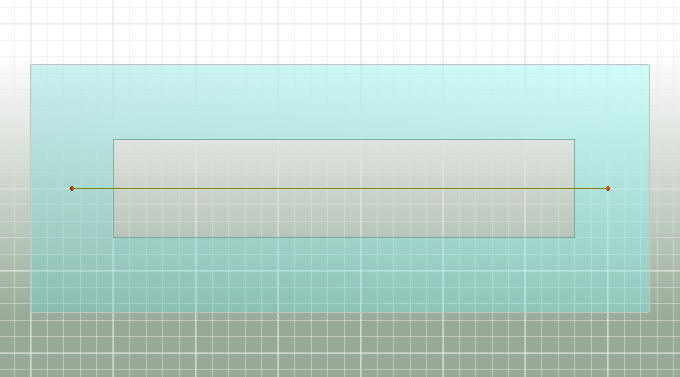
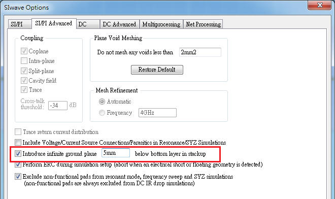
1.3 Keep trace type and introduce infinite plane under bottom layer
-
SIwave for case 2
-
SIwave for case 3
-
SIwave for case 4
-
問題與討論(Q&A)
9.1 What is the difference between trace and plane type?
9.2 What is SIwave 3D DDM? When and how to use it? (important)
9.3 When to set plane type is necessary? When to set trace type is necessary? (important)
9.4 If [Plane Void Meshing] has been set correctly, is there still difference with 3D DDM or not?
![]()
- SIwave for case 1
1.1 Keep trace type
1.2 Convert trace to plane type
1.3 Keep trace type and introduce infinite plane under bottom layer
- SIwave for case 2 (with close and grounded guard trace)
3.1 Keep trace type
3.2 Convert trace to plane type
For this case, converting trace to plane type is better for loss level.
- SIwave for case 3
5.1 Keep trace type
5.2 Convert trace to plane
- SIwave for case 4
7.1 Keep trace type
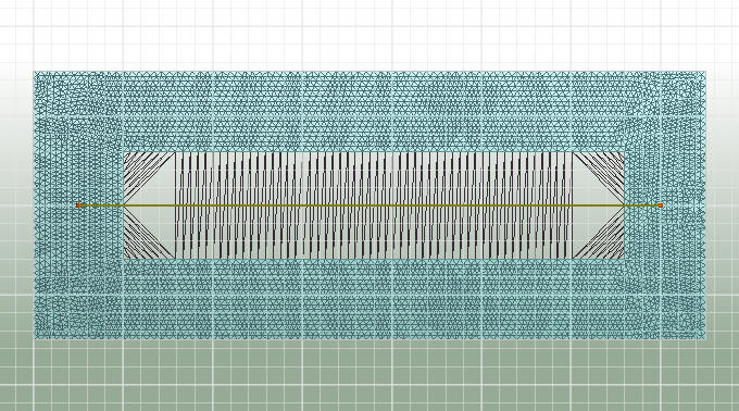
Keep trace type, set [Plane Void Meshing] option as [Automatically determinate which voids to mesh]
It seems that less loss is considered.
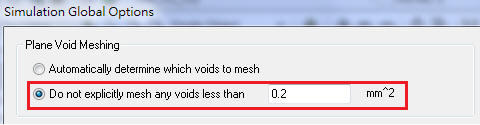
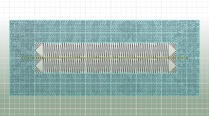
Keep trace type, set [Plane Void Meshing] option as below, and SIwave with 3D DDM (Q3D) (it takes 1 min.)
7.2 Convert trace to plane
Set [Plane Void Meshing] option as [Do not explicitly mesh any voids less than 0.2 mm^2]
- HFSS 3D Layout for case 4
 (it takes 30 min.)
-
問題與討論(Q&A)
9.1 What is the difference between trace and plane type?
Ans:Keep trace type for trace
Convert trace to plane
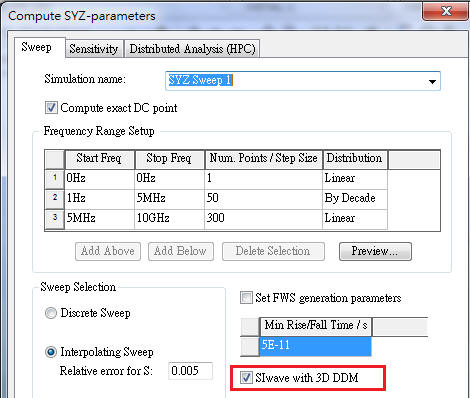
9.2 What is SIwave 3D DDM? When and how to use it?
Ans:For the reference plane with "small holes" (< 0.1 l), SIwave can involve Q3D (quasi-static 3D solver, good for physical length< 0.1 l) to get more accurate result by compensating Y-parameter. To benefit from the 3D DDM, please check [SIwave 3D DDM] and make sure plane void meshing to identify them.
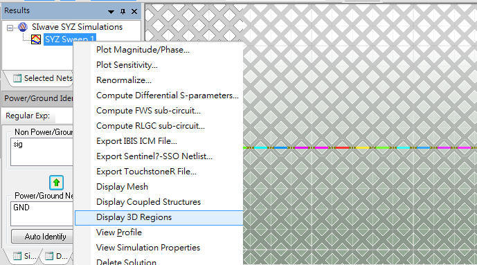
After computing SYZ parameter, you can view where are these 3D regions that SIwave has organized as below
9.3 When to set plane type is necessary? When to set trace type is necessary?
Ans:For resonant mode, plane type is necessary. For 3D DDM (Q3D) and Impedance scan (new from R16), trace type is necessary.
9.4 If [Plane Void Meshing] has been set correctly, is there still difference with 3D DDM or not?
Ans:The answer is [Yes]. To check [3D DDM], it will be closer to HFSS 3/d layout result.
SIwave2014解case4這種meshed plane的題目,除了plane void meshing要設的夠小,還必須核選3D DDM,才能看到~40G處loss忽然大幅增加的現象。但如果是SIwav2015,就算沒有核選3D DDM,只要plane void meshing設的夠小,就可以得到跟3D DDM一樣的結果,並且這結果更接近於HFSS 3D layout的結果。(SIwave R16看來又比R15更準了)
SIwave2014 result
SIwave2015 result
HFSS 3D Layout (R15, R16) result
SIwave以MoM方法計算trace,而以FEM方法計算plane,兩者是不同的技術。一般情況,官方建議trace就維持trace type,不需要刻意去轉成plane type求解。從case2,3,4的例子可以看出,硬將trace type轉成plane type求解,其傳輸線的共振頻點會略為偏高,但對於某些沒有參考地而有close and grounded guard trace的例子(case2),使用plane type所得到的loss程度,反而是比較準的。
10.1 SIwave calculates trace with MoM, but do plane with FEM. They are totally different. In general, to solve trace with trace type, not plane type is proposed. In case, for some special patterns you want to solve trace with plane type, please reconfirm the result with HFSS first.
10.2 For the project with completed reference plane, the last SIwave (R15) can get similar result between trace type and plane type. Based on case2, 3 and 4 results, converting trace to plane will get a little higher resonant frequency points of S11.
10.3 For some of the projects with continue return path, but no completed reference plane (as case2), SIwave with plane type can get better result for loss level.
10.4 SIwave 2014(R15)+[3D DDM] can solve plane with small voids\slots better (more accurate) on very high frequency range.